Table of Contents Link to heading
- Conceptual Modelling
- Conceptual Design Process
- Entity-Relationship Model
- UML Class Diagrams
- Association
- Multiplicity
- Summary of Multiplicity Syntax
- Association Class
- Recursive Relationship (Self Association)
- Aggregation
- Composition
- Strong and Weak Entity Types
- Inheritance
Conceptual Modelling Link to heading
Conceptual modelling is the first phase of database design. Before writing a single line of SQL, the design process requires capturing all data requirements as a visual model — typically a UML Class Diagram or an ER diagram. This model uses a high-level language (4GL) to abstract away implementation details, focusing entirely on what data needs to be stored and how the real-world entities that produce that data relate to each other.
The conceptual model is the artefact shared with stakeholders to validate that the design captures all requirements before any implementation work begins. Changes at this stage cost nothing; changes after physical implementation are expensive.
Conceptual Design Process Link to heading
The design process follows five iterative steps, abbreviated CARMA:
- Classes — Identify all real-world and conceptual objects that need to be stored
- Attributes — For each class, list all attributes needed to capture the required data
- Relationships — Draw association lines between classes that interact
- Multiplicity — Add multiplicity values to each association line
- Again — Verify each class captures only relevant data with no repeating groups or multivalued attributes; if not, decompose and repeat from step 1
More specifically:
- List every real-world and conceptual object about which data must be stored
- Assign attributes to each object — only attributes relevant to that object
- Check each object for Candidate Keys: do they apply to all records in all cases? If yes, select the smallest one as PK. If no, add a Surrogate Key.
- Draw association lines between classes that interact
- Add multiplicity values to each association line
- Verify no class contains repeating values, grouped data, or multivalued attributes — if any are found, decompose into new classes and repeat
Entity-Relationship Model Link to heading
The ER model has three core components:
1. Entities
Entities are the objects the database tracks — both tangible real-world objects and intangible conceptual ones:
- Real-world:
Book,Car,Staff— physically identifiable - Conceptual:
Class,Course,Sale— intangible but meaningful to the business
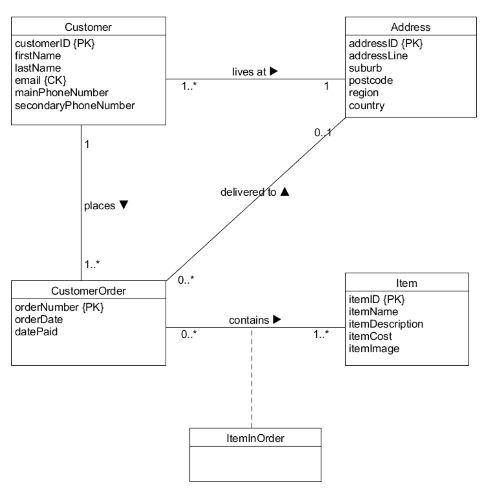
Entities translate to tables (relations) in the final database. Some entities arise as the result of relationships between other entities — for example, StudentEnrolment represents the relationship between Student and Course.
In OOP terms: an entity corresponds to a class, and a tuple in the database corresponds to an instance of that class.
2. Relationships and Multiplicity
Relationships define how entities interact with each other and how many instances of one entity relate to instances of another. Multiplicity constrains these counts and typically reflects real-world business rules.
3. Attributes
Attributes describe the properties of an entity. Each attribute has a domain (data type and acceptable range). In conceptual design, domains are optionally specified:
studentName: varchar(100)— type onlyfavColour: varchar(10) {red, green, blue}— type with constrained range
UML Class Diagrams Link to heading
UML Class Diagrams are the standard notation for conceptual database design:
- A Class corresponds to an entity (a table in the final database)
- An Object is an instance of a class (a row in the table)
- An Association is a relationship between two classes
Association Link to heading
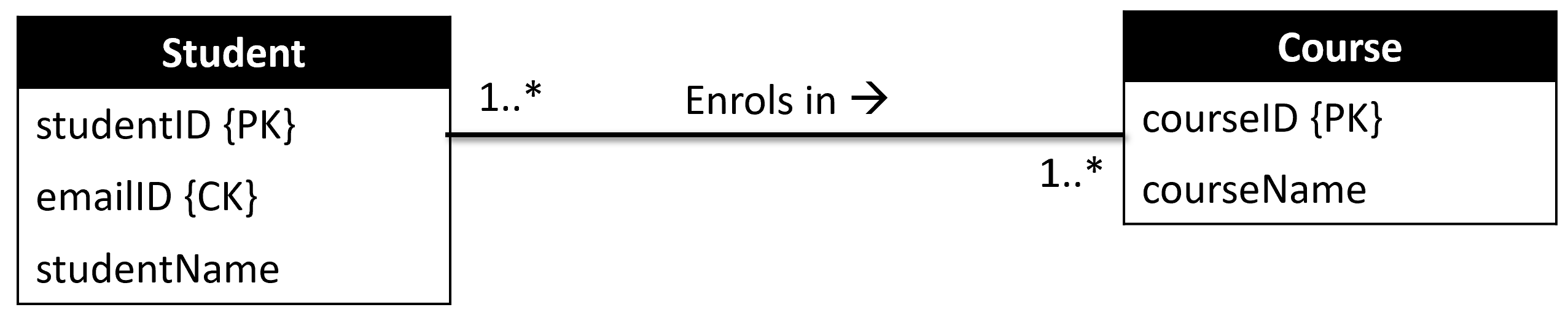
An Association captures the relationship between two classes. If a student enrols in a course, an association line is drawn between Student and Course with a label describing the relationship.
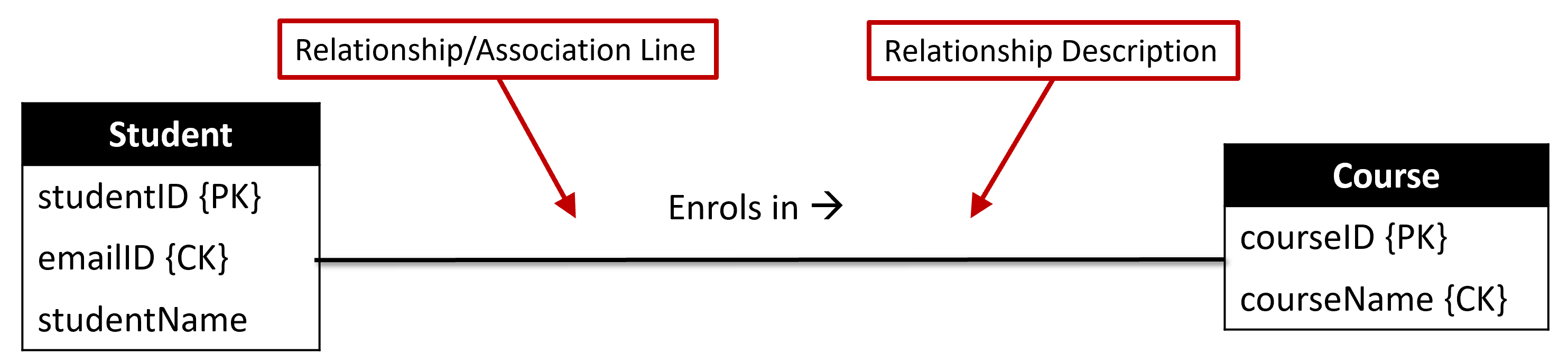
The association line indicates that objects in the Student class can interact with objects in the Course class — and vice versa.
Multiplicity Link to heading
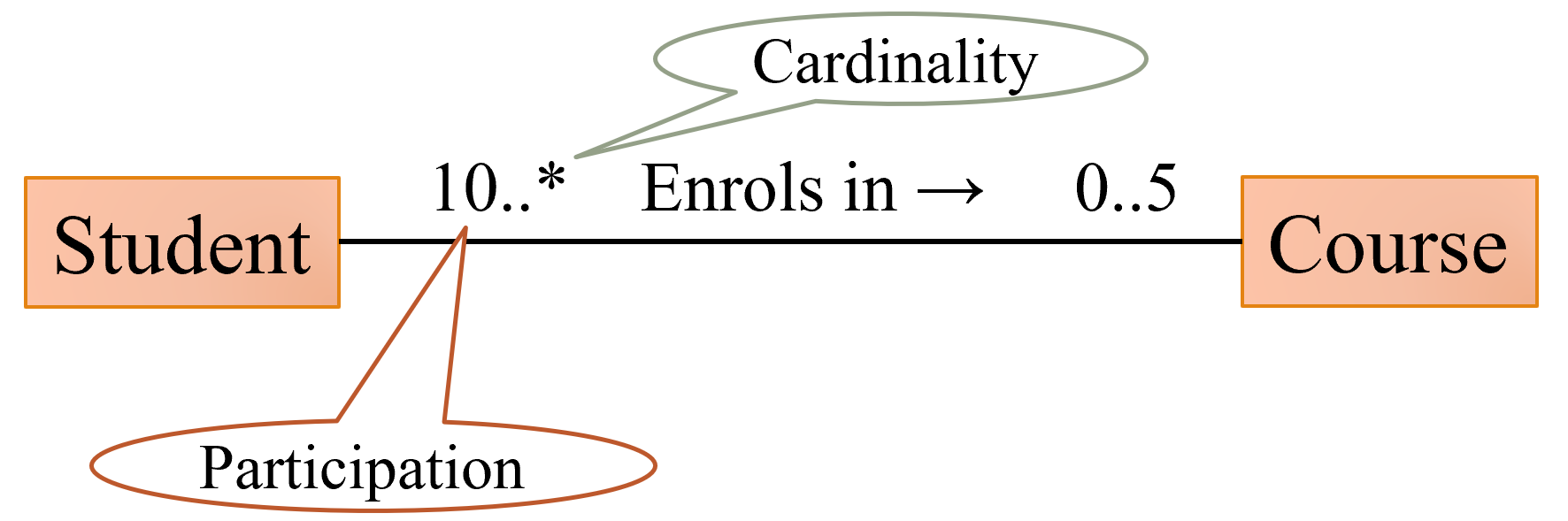
Multiplicity specifies how many instances of one entity can relate to a single instance of another entity through a given association.
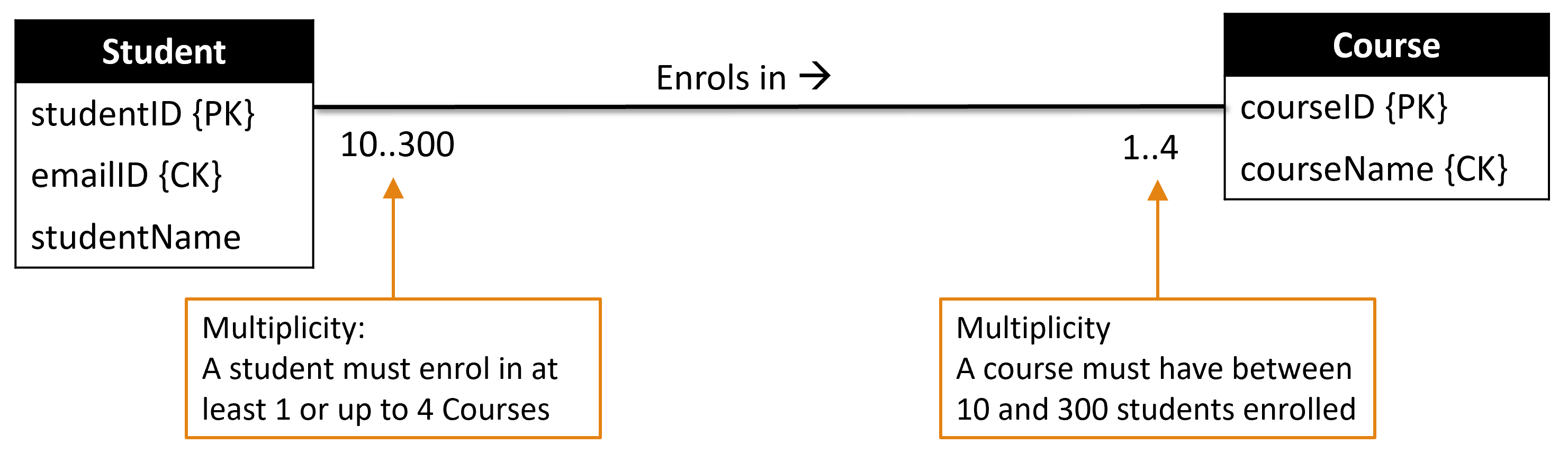
Multiplicity has two components:
Participation — whether all or only some instances of an entity must participate in the relationship (mandatory vs optional):
- A course must have at least 10 students — every course participates
- A student may not enrol in any course — participation is optional
Cardinality — the maximum number of relationship occurrences for an entity:
- A course can have many students
- A student enrols in at most 5 courses
Rules:
- No number or
1implies1..1 - A bare
*implies0..*
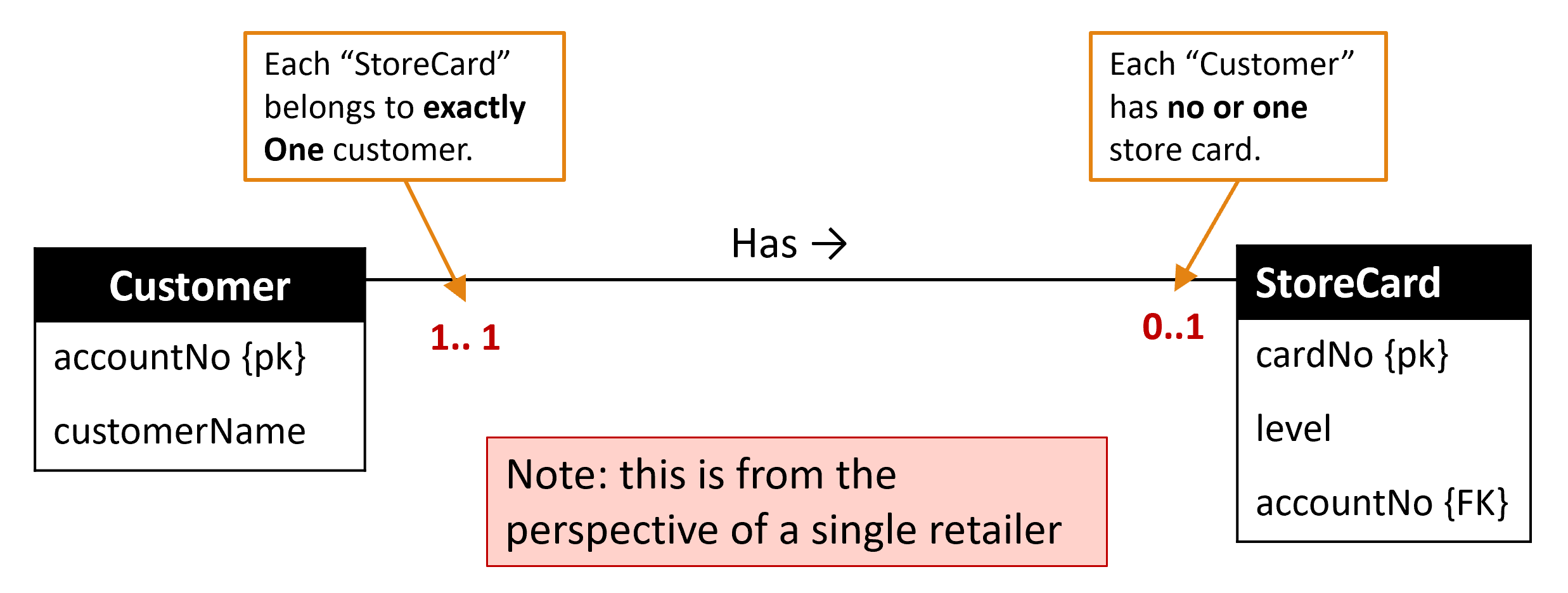
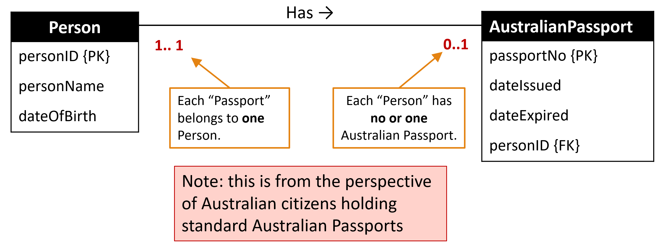
One-to-One (1:1)
Every object on each side associates with at most one on the other side. In the relational schema, place either PK as a FK in the other table. If one side has a 0 minimum (optional), that side holds the FK (so a NULL FK is acceptable without orphaning a mandatory record).
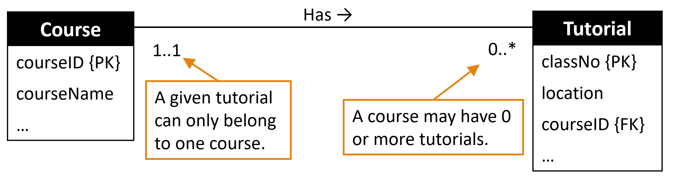
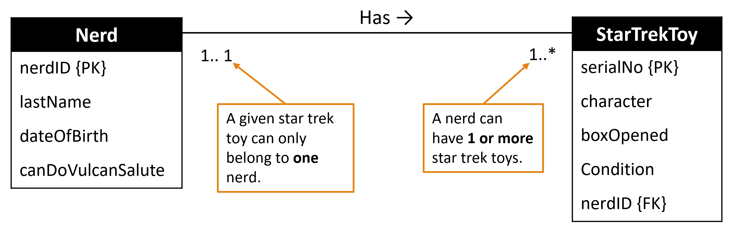
One-to-Many (1:*) and Many-to-One (*:1)
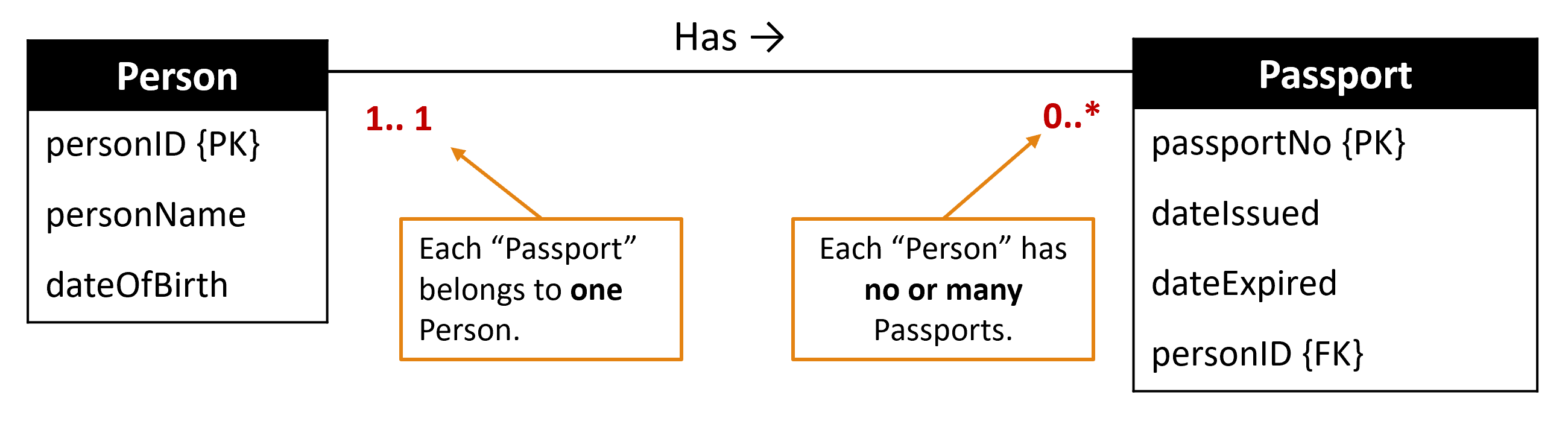
Many instances on one side relate to at most one on the other. Place the PK from the “one” side into the “many” side as a FK.
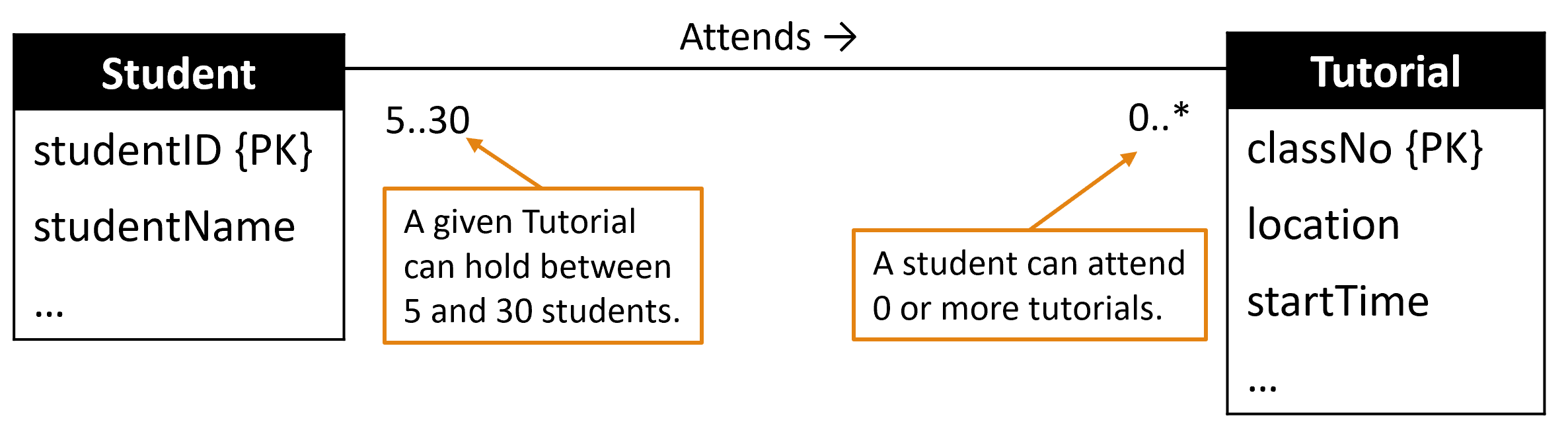
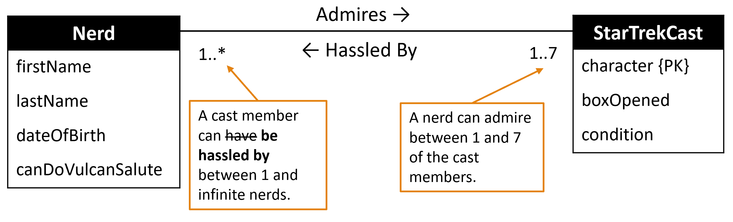
Many-to-Many (*:*)
No restriction on the association. Create an association (junction) table that holds the PKs of both main tables as FKs. These FKs typically form the composite PK of the junction table.
Summary of Multiplicity Syntax Link to heading
| Syntax | Meaning |
|---|---|
0..1 |
Zero or one instance |
1..1 (or 1) |
Exactly one instance |
0..* (or *) |
Zero or more instances |
1..* |
One or more instances |
5..10 |
Minimum 5, maximum 10 instances |
0, 3, 6-8 |
Zero, or three, or six through eight instances |
Note: A relationship end with no number defaults to 1..1.
Association Class Link to heading
An Association Class attaches attributes to the association itself, capturing data that belongs to the relationship rather than to either participating entity.
For example — when a student enrols in a course, what is the dateCommenced and what mark did they receive? Neither dateCommenced nor mark belongs to Student alone or Course alone — they belong to the specific enrolment instance.
Before (no place to store enrolment-specific data):
After (enrolment attributes captured in the association class):
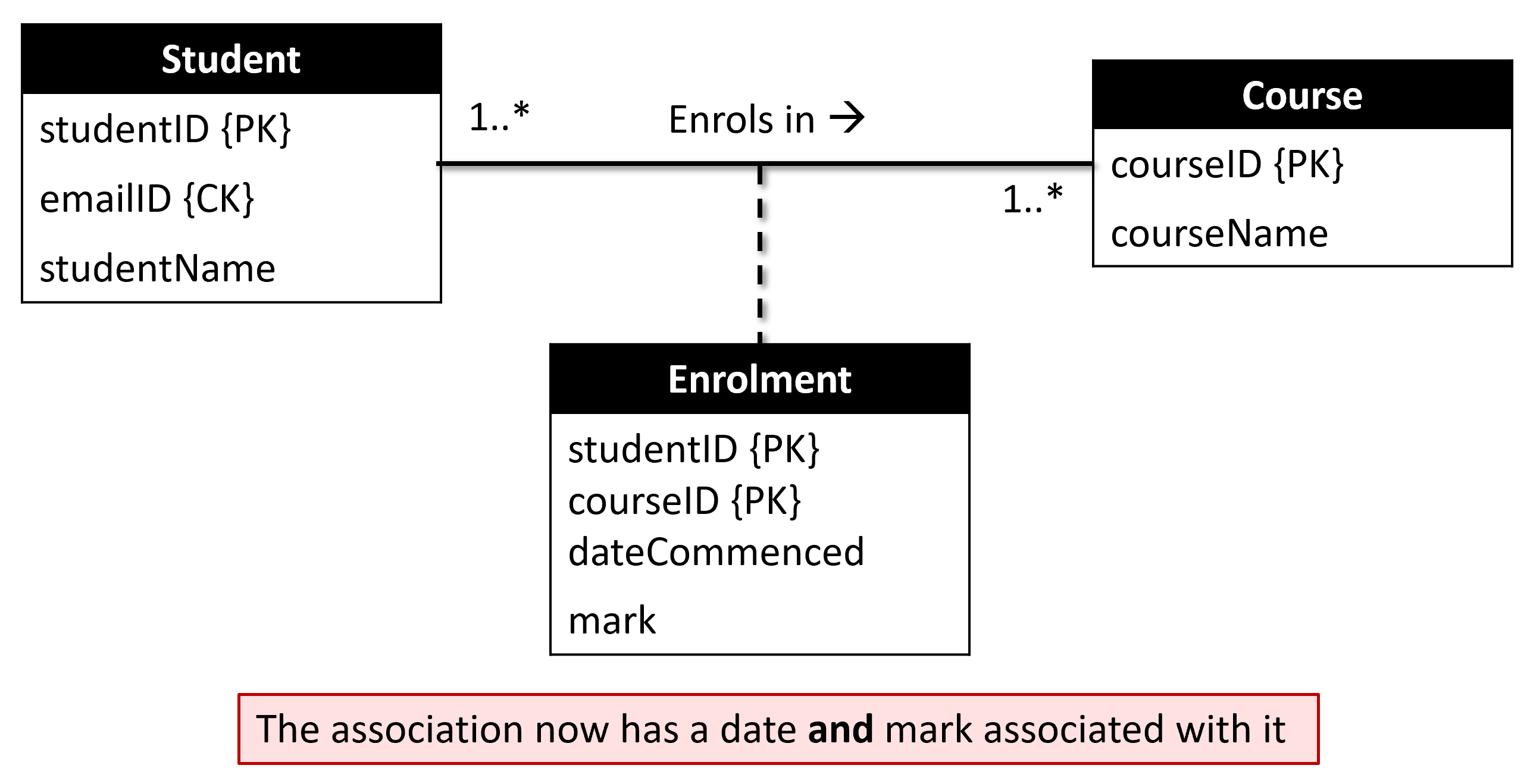
In the relational schema, the association class becomes its own table with the two participating entities’ PKs as FKs.
Recursive Relationship (Self Association) Link to heading
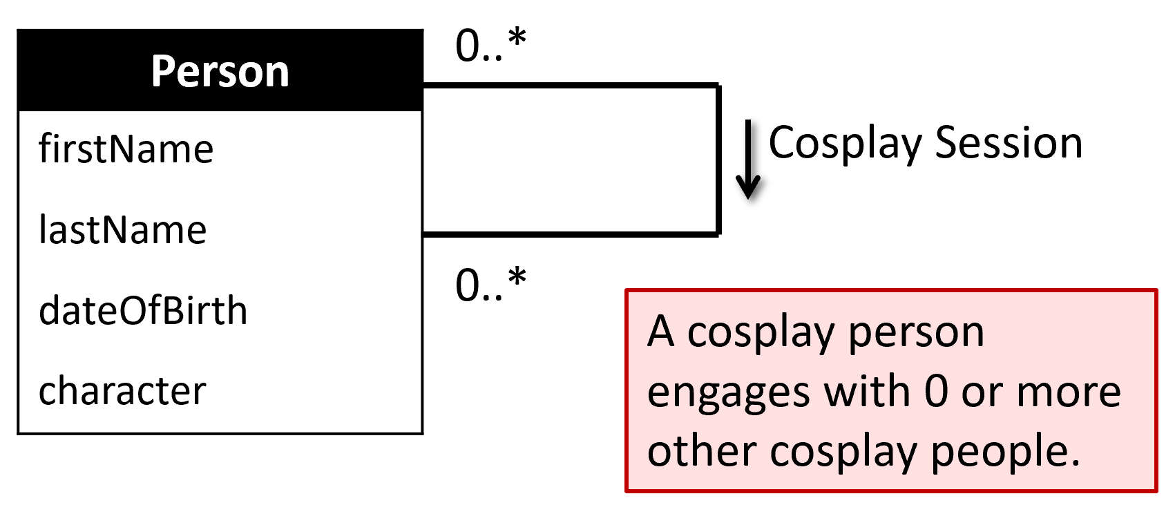
A recursive relationship (or self association) is an association between a class and itself. The same entity type participates more than once in different roles.
Role names are required in a recursive relationship to distinguish each participation:
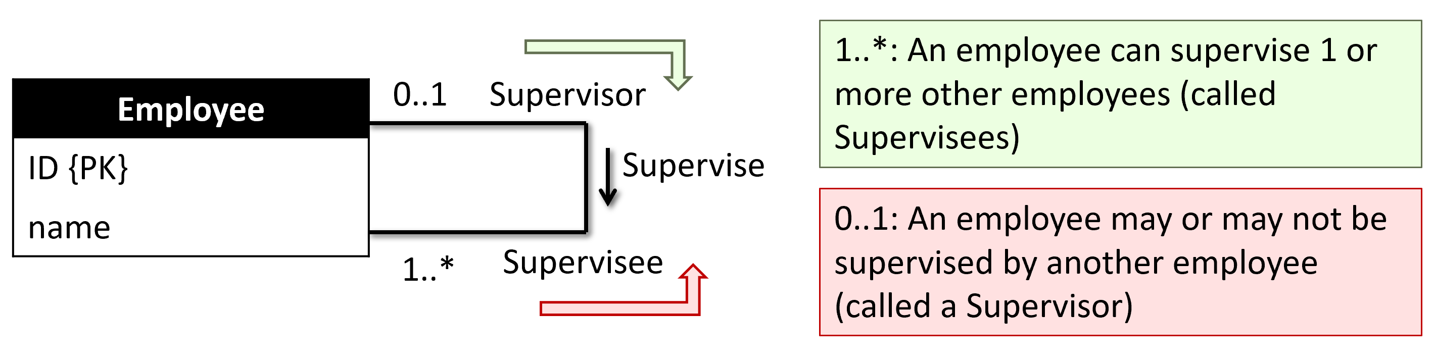
Example: Employee supervises other Employee instances. An employee can be a supervisor, a supervisee, or both. The two roles (supervisor and supervisee) clarify what each end of the relationship means.
In the relational schema, this produces a separate junction table:
Supervision(supervisorID, superviseeID)
FK(supervisorID) → Employee(ID)
FK(superviseeID) → Employee(ID)
Aggregation Link to heading
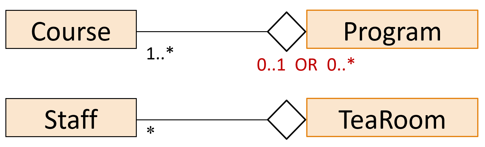
Aggregation represents a has-a or is-part-of relationship where one entity is conceptually a component of another, but can exist independently.
Notation: an unfilled diamond at the whole end of the association line.
Example: A program is an aggregation of courses — a course is part of a program, but deleting the program does not delete the courses.
Composition Link to heading
Composition is a stronger form of aggregation where the lifetime of the parts is bound to the lifetime of the whole. If the whole is deleted, the parts are also deleted.
Notation: a filled diamond at the whole end.
Example: A foot is composed of toes — deleting the foot entity also deletes all its toe entities.
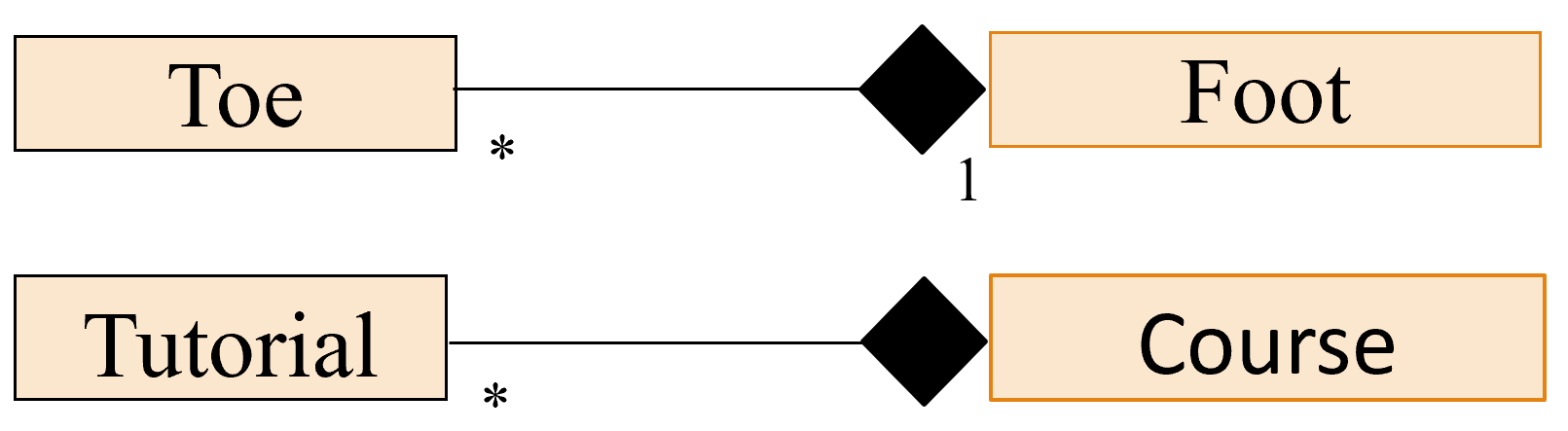
The distinction matters for physical design decisions: aggregation relationships are resolved with a FK; composition relationships may be resolved with CASCADE DELETE constraints to enforce the lifecycle dependency at the database level.
Strong and Weak Entity Types Link to heading
Strong Entity Type: An entity that can be uniquely identified by its own attributes alone, without depending on any other entity.
- Examples:
Student,Building,Competition
Weak Entity Type: An entity whose existence depends on another entity, and whose instances cannot be uniquely identified by their own attributes alone — they require the PK of the parent entity to be fully identified.
- Examples:
Week4Lecture(which subject? which semester? which year?),StudentAssignment(which subject? which semester?),BuildingRoom
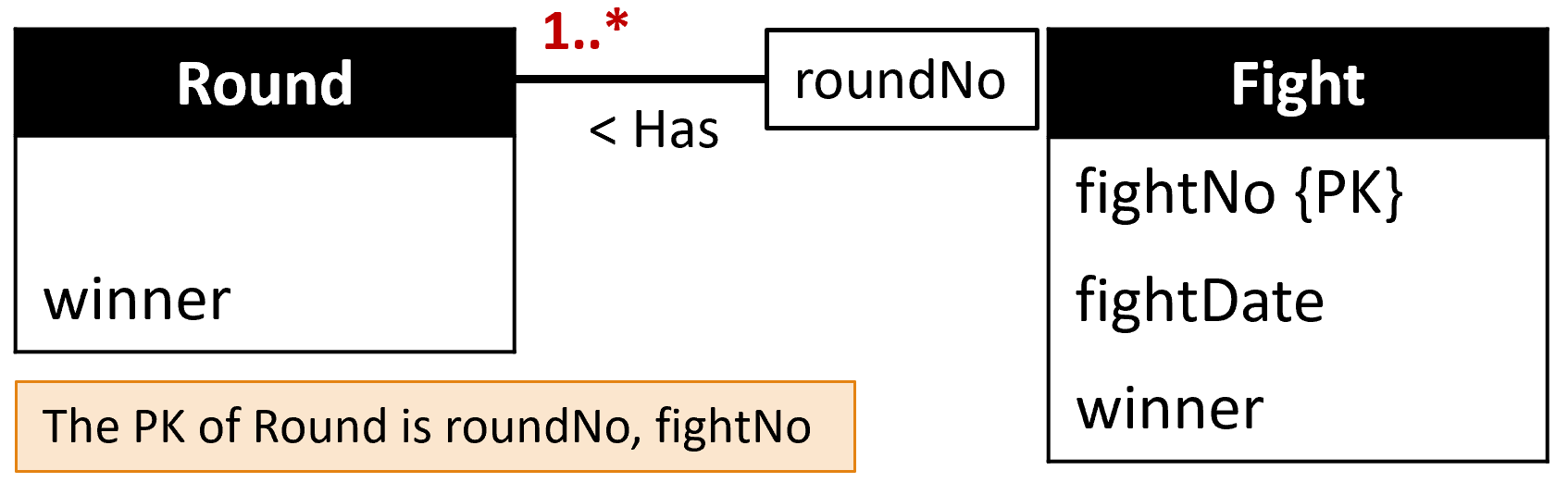
In the relational schema, a weak entity’s PK is always a composite that includes the parent entity’s PK.
Inheritance Link to heading
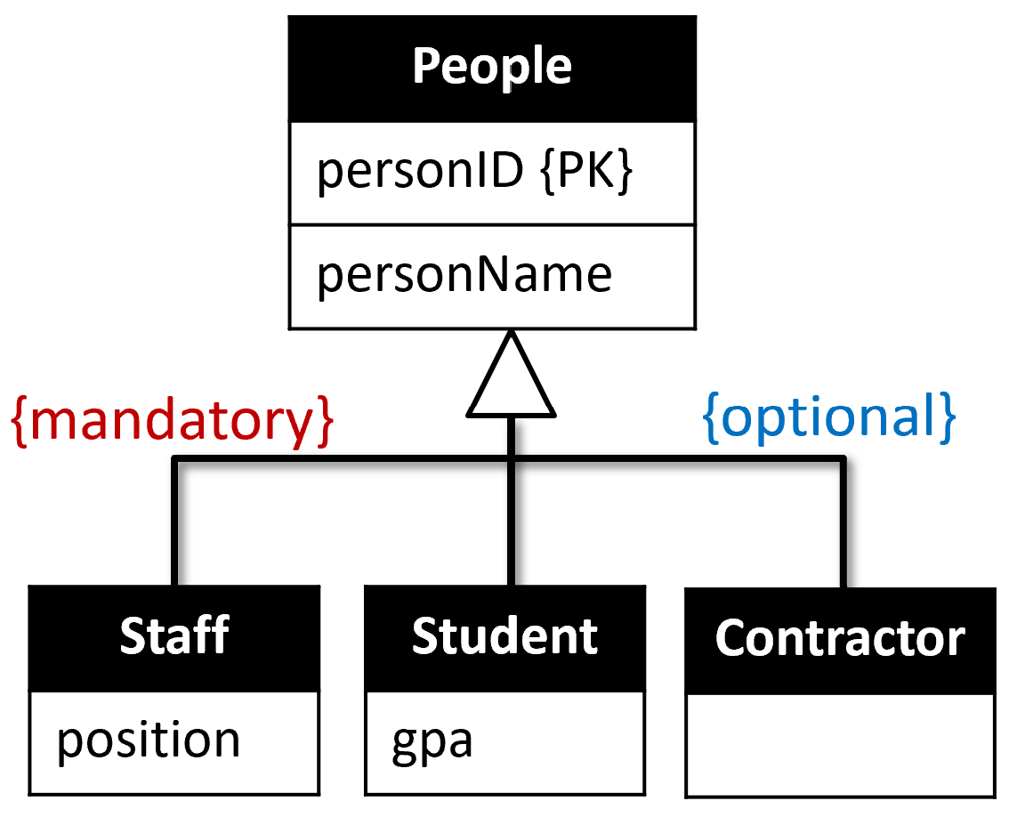
Inheritance models a Generalisation/Specialisation hierarchy where a general entity type (superclass) has one or more specialised subtypes (subclasses).
Superclass: A general entity type with common attributes shared by all subtypes. Example: Person(personID, personName).
Subclass: A specialisation of the superclass with additional attributes specific to that subtype. Example: Staff and Student are subclasses of Person.
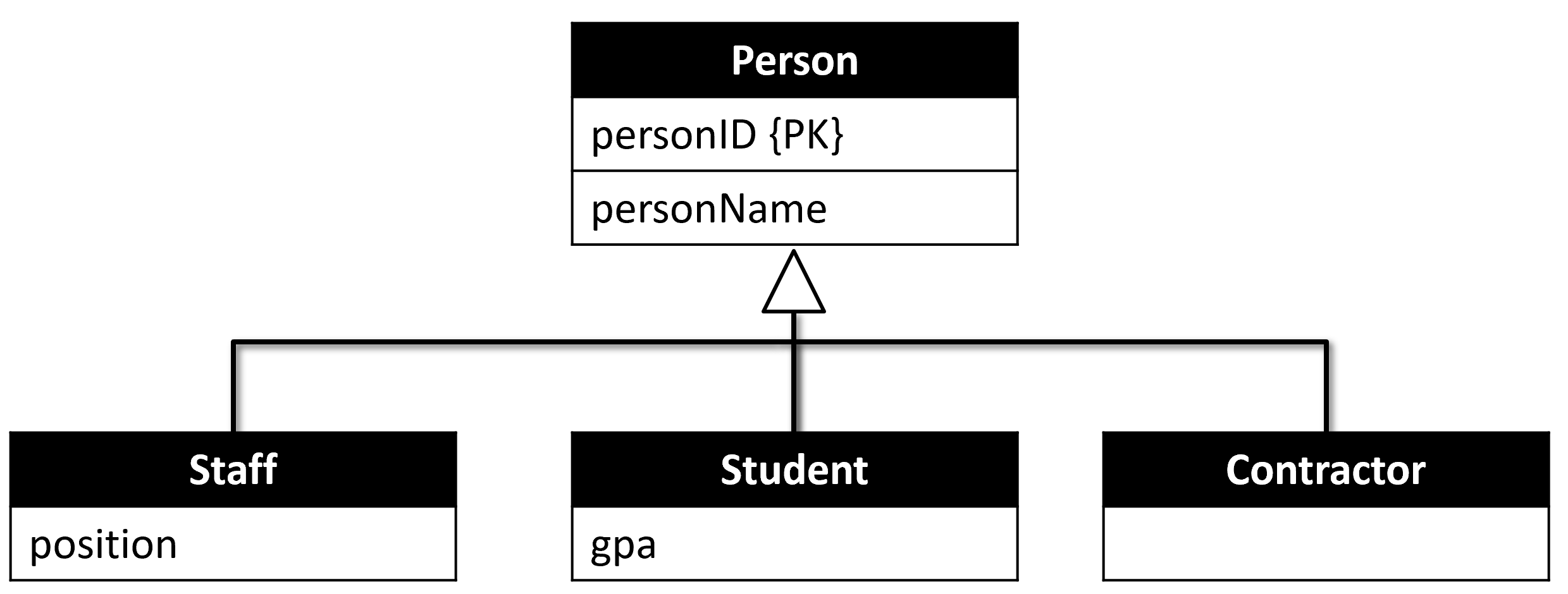
Attribute Inheritance: Subclasses inherit all attributes from their superclass. A Student has both gpa (its own attribute) and personName, personID (inherited from Person).
Primary Key Inheritance: Subclasses inherit the PK of the superclass. The inherited PK serves as both the PK of the subclass and as a FK referencing the superclass.
Specialisation: Identifying distinguishing characteristics of subclasses from a common superclass (Person → Student, Staff, Contractor).
Generalisation: Identifying shared characteristics of multiple entities to form a superclass.
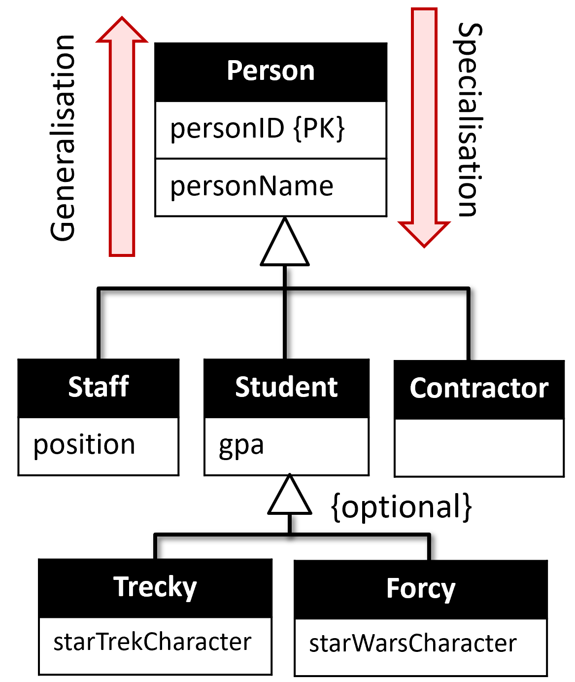
Constraints on the Specialisation:
| Constraint | Meaning |
|---|---|
| Optional participation (default) | A person may not belong to any subclass |
| Mandatory participation | A person must belong to at least one subclass |
| Disjoint (OR) | A person belongs to exactly one subclass |
| Non-Disjoint (AND) — overlapping | A person may belong to more than one subclass |